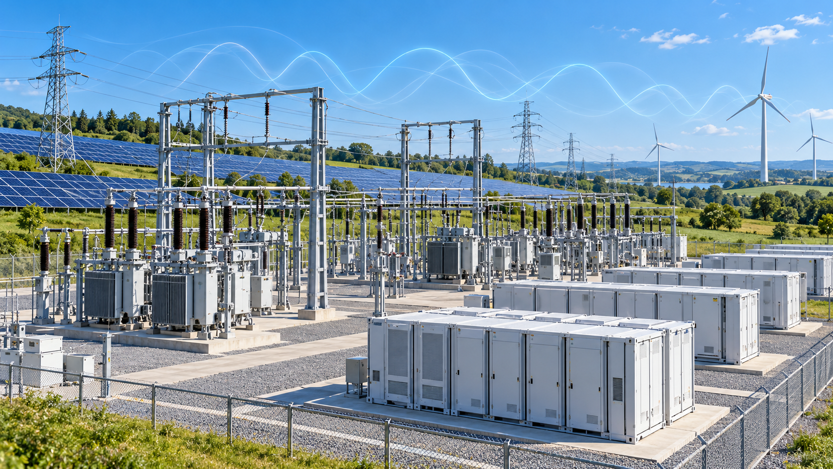
Editorial illustration. Waveforms are conceptual, not measured grid data.
The Invisible Battle Inside the Grid — Part 3 of 7
For generations, power-system engineers have studied the subtle movements of enormous rotating machines.
When a disturbance occurs on an interconnected electricity network, synchronous generators do not always respond in perfect unison. Their rotors accelerate and decelerate, exchanging energy through the transmission system.
Sometimes those movements produce oscillations.
A generator may swing against nearby machines. Groups of generators in one region may oscillate against generators hundreds of miles away. If the oscillations are poorly damped, their magnitude may persist or increase, threatening stable operation.
These phenomena have been studied for decades.
Engineers developed mathematical models, monitoring systems, and specialized controls to understand and manage them.
But the electric grid is changing.
Solar plants, battery energy storage systems, modern wind turbines, HVDC transmission systems, and other power electronic technologies are introducing new dynamic behavior into electricity networks.
Unlike traditional synchronous machines, these devices depend heavily on high-speed electronic controls.
Their response to a disturbance is shaped by software algorithms, measurement systems, semiconductor limits, and interactions with the surrounding network.
This creates an increasingly important stability challenge.
The grid is no longer influenced only by how rotating machines interact. It is also influenced by how independently designed digital controllers respond to one another.
And some of those interactions can produce oscillations that traditional power-system studies were not designed to capture.
The Oscillations Engineers Already Understand
Traditional power-system stability analysis developed around the electromechanical behavior of synchronous generators.
When a disturbance changes the balance between mechanical input and electrical output, generator rotors accelerate or decelerate.
The resulting changes in rotor angle influence power flows across the transmission network.
Under some conditions, the system oscillates as generators exchange energy.
Two broad categories have long been important.
Local oscillations generally involve one generator or a group of generators swinging against the surrounding power system.
These modes often occur at frequencies of approximately 1 to 2 hertz, although the actual range depends on the network and equipment.
Inter-area oscillations involve groups of generators in different regions swinging against one another.
These typically occur at lower frequencies, often around 0.1 to 1 hertz.
Their significance can extend across large interconnected networks.
Engineers analyze these modes using mathematical tools that describe oscillation frequency, damping, mode shape, and the participation of individual machines or controls.
The objective is not simply to determine whether an oscillation exists.
It is to understand whether the oscillation will decay following a disturbance or persist in a way that threatens reliable operation.
These methods remain essential.
However, the increasing presence of power electronic converters means that not every important oscillation can be explained through generator rotor dynamics.
When the Controller Becomes Part of the Oscillation
A modern inverter is more than an electrical conversion device.
It is a tightly controlled system that continuously measures network conditions and adjusts its electrical output.
A typical grid-following inverter may contain several interacting control functions.
A phase-locked loop estimates the electrical phase angle of the network.
Current controllers regulate the converter’s electrical output.
Active-power and reactive-power controllers establish operating targets.
Voltage-control functions may adjust the inverter’s response to changing network conditions.
DC-link controls help maintain the balance between energy entering and leaving the converter.
These functions operate at different speeds and interact with the physical electrical network.
Each control loop is designed to achieve a particular objective.
But the combined response of multiple control loops is not always obvious from their individual designs.
An inverter may perform correctly when tested against a strong, idealized electrical source.
Its behavior can change when connected to a network with higher impedance, lower short-circuit strength, or other nearby converters.
A control action changes the electrical conditions at the connection point.
Those changes are measured by the inverter and may trigger further control actions.
If the resulting feedback is poorly damped, an oscillation can develop.
The oscillation may involve a single converter and the surrounding network.
It may involve several converters.
Or it may emerge through interactions between power electronic equipment and conventional electrical machines.
This broader class of behavior is often described as converter-driven stability.
It is becoming one of the defining challenges of modern power-system analysis.
Subsynchronous Oscillations: An Old Problem With New Mechanisms
One important category is subsynchronous oscillation.
The term generally describes oscillatory phenomena involving electrical frequencies below the fundamental power-system frequency.
In a 60-hertz network, these components occur below 60 hertz. In a 50-hertz network, the corresponding reference is 50 hertz.
Subsynchronous phenomena are not new.
For decades, engineers have investigated subsynchronous resonance involving turbine-generators and series-compensated transmission systems.
Under certain conditions, electrical-network dynamics can interact with mechanical torsional modes of a turbine-generator shaft.
Those interactions can produce damaging oscillations if they are not adequately controlled.
The expansion of inverter-based resources has introduced additional mechanisms.
Modern wind turbines, solar plants, and other converter-connected equipment can interact with the impedance characteristics of transmission networks.
Series compensation, converter control settings, and network operating conditions may influence the resulting behavior.
In some cases, the dominant mechanism is associated with converter controls rather than mechanical shaft dynamics.
This distinction matters because the appropriate mitigation depends on the cause.
A problem originating in a turbine-generator torsional interaction is not necessarily addressed in the same way as an oscillation involving converter controls and network impedance.
The measured frequency alone does not identify the mechanism.
Engineers must determine which equipment and dynamic processes are participating in the oscillation.
That requires accurate models, appropriate measurements, and analysis methods capable of representing the relevant electrical and control-system behavior.
The Phase-Locked Loop: When Synchronization Becomes a Challenge
Among the control functions used in grid-following inverters, the phase-locked loop has attracted particular attention.
Its purpose is to estimate the phase angle and frequency of the grid voltage.
The inverter uses this information to synchronize its operation with the electrical network.
Under suitable conditions, this approach works effectively.
In a strong network, the voltage waveform at the inverter’s connection point is relatively insensitive to changes in the inverter’s injected current.
The phase-locked loop can track the electrical reference without strongly influencing the conditions it is measuring.
In a weak network, the relationship becomes more complicated.
The inverter’s current can produce larger changes in the voltage magnitude and phase angle at its connection point.
The phase-locked loop responds to those changes.
Its response influences the inverter’s current-control system.
That current response can then produce further changes in the network voltage.
The result is a feedback relationship between the inverter and the grid.
If the control settings and network characteristics are unfavorable, the interaction may reduce damping or cause instability.
The problem is not that phase-locked loops are inherently unstable.
Their performance depends on their design, tuning, operating conditions, and the strength of the surrounding network.
A phase-locked loop that performs satisfactorily in one electrical system may require different settings in another.
This is particularly important when renewable plants are connected in remote locations where transmission infrastructure is relatively weak.
It also illustrates why inverter stability cannot be evaluated solely from equipment ratings.
A converter’s dynamic response can be just as important as its maximum power output.
When Multiple Inverters Begin to Interact
The challenge becomes more complex when several inverter-based resources operate within the same electrical region.
Consider a transmission network containing multiple solar plants, wind farms, and battery storage facilities.
Each installation may have its own inverter manufacturer.
Each may use different control software.
Each may have different operating limits, control bandwidths, and protection settings.
Individually, the equipment may satisfy its performance requirements.
But the plants are not electrically isolated.
They share the surrounding network.
When one facility changes its electrical output, the resulting voltage response may be detected by neighboring facilities.
Those facilities then respond through their own controls.
The combined interaction can produce behavior that would not appear when each plant is studied independently.
In some circumstances, similar control characteristics across multiple installations can contribute to a poorly damped mode.
In others, interactions between different control architectures may be important.
The network configuration also matters.
A transmission outage, switching operation, or change in generation dispatch can alter the impedance seen by connected converters.
A system that is stable under one operating condition may have smaller stability margins under another.
This creates a difficult planning problem.
The grid is becoming a network of independently developed control systems whose behavior must remain coordinated across a wide range of conditions.
Individual equipment compliance does not automatically guarantee stable performance when many devices operate together.
System-level analysis remains essential.
The Hidden Interactions Inside Converter Controls
Even a single converter contains multiple control functions that can influence one another.
Outer control loops may regulate active power, reactive power, voltage, or DC-link conditions.
Inner control loops typically manage faster electrical quantities, such as converter current.
Synchronization functions establish the phase reference used by grid-following controls.
Filtering, measurement delays, and digital processing affect how quickly the converter responds.
These control functions are designed to operate together.
However, their dynamic interactions depend on their bandwidths, gains, limits, and the electrical characteristics of the connected network.
If control loops respond on similar timescales, their interactions may become particularly important.
A voltage regulator may attempt to correct a disturbance while a current controller is simultaneously responding to the same change.
A synchronization controller may alter the reference used by another control function.
Current limits may change the converter’s behavior during a severe disturbance.
The resulting system can exhibit oscillatory modes that are not apparent from a simplified representation of the converter.
This is one reason detailed equipment models are increasingly important.
The objective is not to model every semiconductor switching event in every study.
It is to represent the dynamic processes necessary to answer the engineering question.
Different oscillation mechanisms require different levels of modeling detail.
Why Traditional Stability Studies May Miss the Problem
Conventional power-system stability tools were developed primarily to analyze the behavior of interconnected synchronous machines and their controls.
They remain highly effective for many applications.
Positive-sequence dynamic simulation, for example, continues to play an important role in studying large interconnected networks and electromechanical disturbances.
But some converter-driven interactions involve faster dynamics, unbalanced conditions, or control details that simplified models do not adequately represent.
In these cases, additional analysis methods may be necessary.
Electromagnetic transient simulation, commonly called EMT simulation, can represent electrical waveforms and detailed converter dynamics at a much finer timescale than conventional electromechanical studies.
Depending on the modeling approach, EMT simulations can include switching behavior or averaged converter representations.
They are particularly valuable when fast control interactions or detailed network characteristics are important.
Impedance-based stability analysis provides another perspective.
Rather than focusing only on time-domain responses, engineers examine how the dynamic impedance of a converter interacts with the impedance of the surrounding electrical network.
This can help identify frequencies where unfavorable interactions may occur.
Small-signal analysis can reveal oscillatory modes and their damping characteristics.
Hardware-in-the-loop testing offers an additional capability by allowing actual control equipment to interact with a simulated electrical system.
These approaches are complementary.
No single method is sufficient for every stability problem.
The central requirement is to match the analysis technique to the physical and control-system mechanisms being investigated.
The Growing Importance of Accurate Inverter Models
One of the most important lessons from converter-related stability investigations is that model accuracy matters.
A simulation can only reproduce behavior represented within its models.
If an inverter’s control parameters are incorrect, the simulated response may differ from the actual equipment.
If important control functions are omitted, the study may fail to identify an interaction.
If plant-level controls are represented inaccurately, engineers may misunderstand how an entire renewable facility responds to a disturbance.
The challenge is compounded when several plants use different equipment and control architectures.
Utilities and system operators may need to coordinate with multiple manufacturers to obtain suitable models.
Model confidentiality and proprietary control designs can complicate that process.
However, reliable system studies require enough information to represent the behavior relevant to grid stability.
Model validation is therefore as important as model development.
Measurements from commissioning tests and actual operating events can help determine whether simulations reproduce observed responses.
Where discrepancies are found, models may need to be updated.
As inverter penetration increases, the quality of this process becomes an increasingly important part of system reliability.
Detecting Oscillations Before They Become Reliability Events
Studying potential oscillations before equipment is connected is essential.
But planning studies cannot anticipate every future operating condition.
Transmission configurations change.
Generation dispatch changes.
Equipment settings are modified.
New facilities are added to existing networks.
These changes can alter system dynamics.
Utilities therefore also need effective monitoring.
Phasor measurement units, or PMUs, provide synchronized measurements of electrical quantities across geographically separated locations.
When deployed within wide-area measurement systems, they can help engineers identify oscillatory behavior and examine how disturbances propagate through the network.
Advanced analysis can estimate oscillation frequency, damping, and the relative response of different locations.
However, measurement capability must be matched to the phenomenon being investigated.
Conventional synchrophasor reporting rates are well suited to many low-frequency oscillations but may be insufficient to resolve faster converter-driven dynamics.
High-speed waveform recording and other specialized measurements may be required.
Monitoring can reveal that an oscillation exists.
Determining its cause may require additional analysis, including detailed models, operating records, and information about equipment controls.
That distinction is important.
An oscillation detected at a substation is not necessarily caused by the equipment located there.
Electrical oscillations can propagate through the network, making the apparent location of a measured disturbance different from its actual source.
Effective diagnosis requires a system-level perspective.
Can Grid-Forming Inverters Reduce the Risk?
Grid-forming inverter technology offers a potentially important tool for improving stability in converter-rich networks.
Unlike conventional grid-following controls, grid-forming controls are designed to establish and regulate a voltage waveform rather than depend primarily on tracking an external phase reference.
This can provide useful capabilities in systems with limited synchronous generation.
Grid-forming converters may support voltage and frequency behavior, contribute to stable operation in weak networks, and provide damping functions when appropriately designed.
Battery energy storage systems are particularly relevant because they can combine grid-forming controls with rapidly adjustable active-power output.
However, grid-forming operation does not eliminate every converter-driven stability risk.
Multiple grid-forming devices can also interact.
Their behavior depends on control design, network characteristics, current limits, and available energy.
A grid-forming inverter that performs well in one system may require different tuning or operating arrangements in another.
The appropriate objective is not simply to replace every grid-following inverter with a grid-forming device.
It is to develop a coordinated combination of resources and controls that provides the required stability performance.
That requires detailed engineering studies and validation under realistic operating conditions.
A Different Way to Think About Grid Stability
The emergence of converter-driven oscillations does not mean that renewable generation is inherently unstable.
Nor does it mean that the traditional methods of power-system engineering are obsolete.
The fundamental principles of electrical-network dynamics, feedback control, and system stability remain relevant.
What is changing is the equipment that participates in those dynamics.
In a conventional power system, engineers often begin by examining the movement of synchronous-machine rotors.
In a converter-rich system, they may need to examine phase-locked loops, current controllers, voltage regulators, DC-link dynamics, and interactions between multiple power electronic devices.
The underlying challenge is still to maintain stable operation following disturbances.
But the mechanisms can be different.
A system may have adequate generation capacity and still experience a converter-control instability.
A renewable plant may meet its steady-state operating requirements while contributing to an unexpected dynamic interaction.
A network may operate satisfactorily under normal conditions but become vulnerable after a transmission outage changes its electrical strength.
These possibilities make detailed dynamic analysis increasingly important.
They also highlight the need for closer coordination between equipment manufacturers, utilities, system operators, and researchers.
The next generation of stability engineering will depend on understanding not only the behavior of individual devices, but also the collective response of the electrical network.
The New Oscillations Are an Engineering Warning
The electric grid is becoming more electronically controlled.
That transformation brings substantial benefits.
Power electronic converters offer fast response, flexible control, and new ways to integrate generation and storage.
They can provide capabilities that were difficult or impossible to obtain from conventional equipment alone.
But those capabilities introduce new interactions that must be understood.
Subsynchronous phenomena can arise through mechanisms different from those historically associated with turbine-generators.
Phase-locked loops can interact with weak networks.
Multiple inverter plants can influence one another through shared electrical infrastructure.
Control loops operating at different speeds can produce unexpected dynamic behavior.
And simplified stability models may not capture every mechanism that matters.
None of these challenges makes a stable inverter-rich grid impossible.
They make engineering discipline more important.
The objective is to identify potential interactions before they become operational problems, validate equipment behavior, and develop controls that remain stable across realistic network conditions.
For decades, power-system engineers asked how large rotating machines would respond to disturbances and interact across interconnected networks.
That question remains important.
But a new one is emerging alongside it.
How will thousands of independently controlled power electronic devices behave when they are connected through the same electric grid?
The answer will help determine how reliably the next generation of power systems can operate.
Coming Next in Part 4
PMUs, Synchrophasors, and AI: The New Oscillation Radar
Part 4 examines how synchronized measurements, wide-area monitoring, advanced signal processing, and emerging analytical methods are changing the way utilities detect, identify, and investigate oscillations before they threaten system reliability.
Part 4 forthcoming.
← Part 2: From Rotating Machines to Digital Controllers · Start with Part 1 · All insights →